< Information System Development Part 2 | Java & Friends Activities >
Information System Development Process Example Part 3
2.2.5 Collaboration Diagrams
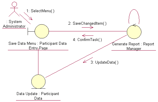
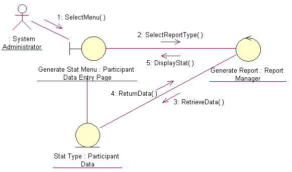
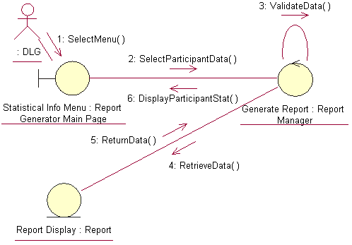
Interaction modeling captures between objects needed to execute a use case. Interaction models are used in more advanced stages of requirements analysis, when a basic class model is known or stabilized, so that the references to objects are backed by the class model. Basically, interaction is a set of messages in some behavior those are exchanged between objects across links. Keep in mind the main distinction between the activity modeling and the interaction modeling. Usually, both capture the behavior of a single use case. However, the activity modeling is done at a higher level of abstraction that is, it shows the sequencing of events without assigning the events to objects. The interaction modeling shows the sequencing of events (messages) between collaborating objects. As said before, there are two kinds of interaction diagram: the sequence diagram and the collaboration diagram. They can be used interchangeably and, indeed, many CASE tools such as Rational Rose support an automatic conversion from one model to the other. The difference is in emphasis. The sequence models concentrate on time sequences and the collaboration models stress more on object relationships. Base on the reference books, the sequence diagrams used in the requirements analysis and collaboration diagrams in the system design. The following are the collaboration diagrams generated automatically from the previous sequence diagram using Rational Rose.
|

Figure 2.24: Add Activity collaboration diagram

Figure 2.25: Delete Activity collaboration diagram

Figure 2.26: Save Changed Item collaboration diagram

Figure 2.27: Generate Report collaboration diagram

Figure 2.28: Add Participant Data collaboration diagram

Figure 2.29: Delete Participant Data collaboration diagram

Figure 2.30: Change Participant Data collaboration diagram

Figure 2.31: Save Changed Data collaboration diagram
-------------------------------------------------------------------------------------------------------------------------------------------------------------------------------------
-------------------------------------------------------------------------------------------------------------------------------------------------------------------------------------

Figure 2.32: Generate Participant Statistical Information collaboration diagram

Figure 2.33: Produce CeC Report collaboration diagram

Figure 2.34: Produce Statistical Information collaboration diagram

Figure 2.35: Login System collaboration diagram
------------------------------------------------------------------------------------------------------------------------------------------
-----------------------------------------------------------------------------------------------------------------------------------------

Figure 2.36: Logoff System collaboration diagram
3. Conclusion
As mentioned in the scope and objective of this project, we successfully completed the analysis and design stages of the RCUMS system development satisfying the minimum requirements. However we are aware that our design has many shortcomings. We found that those stages need more reviews, feedbacks and comments because many tasks need to be repeated iteratively in order to get a very clean and optimized design. For example the class diagrams that we have created didn’t have relationships or collaborations and the flow-of-event documents just consist the basic items. Other example is the incomplete use case diagrams that just based on the main and sub flows. There are no diagrams for the alternative and exceptional flows were produced and these were carried on to the next stage of the sequence and collaboration diagrams creation.
We also aware about the confusion regarding the order of the stages implemented when referring some of the recommended reference books, for example it is the flow-of-event or use case diagrams must be done first? Or either one can be the first. Contradict to the steps done in this project, we found that it is easier to find actors, use cases and draw the use case diagrams first and then prepare the narrative description in the flow-of-event documents. Moreover there are more steps in the analysis and design stages that we do not have time and energy to be exposed for, such as building the activity diagrams and we also miss the behavioral model stage, the state chart diagram development. Regardless of the shortcomings, we have learnt a lot through the hands-on approach of this subject matter and appreciate the tedious and monotonous tasks of the system development process in building medium to large scale software.
4. References
-
Ambler, S. Agile Modeling: Effective Practices for Extreme Programming and Unified Process. John Wiley, New York, 2002.
-
Booch, G. Object-Oriented Analysis and Design with Applications, 2nd ed. Benjamin/Cummings, Redwood City, CA, 1994.
-
Booch, G., Rumbaugh, J., and Jacobson, I. The Unified Modeling Language User Guide. Addison-Wesley, Reading, MA, 1999.
-
Dobing, B. and Parsons, J. Understanding the role of Use Cases in UML: A review and research agenda. Journal of Database Management 11, 4 (2000), 28-36.
5. List of Figures
Figure 2.1: Four main RCUMS use case diagrams
Figure 2.2: Manage CeC Reports use case diagram
Figure 2.3: Manage Participant Data use case diagram
Figure 2.4: Manipulate CeC Report use case diagram
Figure 2.5: Authenticate User use case diagram
Figure 2.6: Rules in building the sequence diagram
Figure 2.7: Class’s three compartments
Figure 2.8: Boundary classes
Figure 2.9: Controller class
Figure 2.10: Entity classes
Figure 2.11: Add Activity sequence diagram
Figure 2.12: Delete Activity sequence diagram
Figure 2.13: Save Changed Item sequence diagram
Figure 2.14: Generate Report sequence diagram
Figure 2.15: Add Participant Data sequence diagram
Figure 2.16: Delete Participant Data sequence diagram
Figure 2.17: Change Participant Data sequence diagram
Figure 2.18: Save Changed Data sequence diagram
Figure 2.19: Generate Participant Statistical Information sequence diagram
Figure 2.20: Produce CeC Report sequence diagram
Figure 2.21: Produce Statistical Information sequence diagram
Figure 2.22: Login System sequence diagram
Figure 2.23: Logoff System sequence diagram
Figure 2.24: Add Activity collaboration diagram
Figure 2.25: Delete Activity collaboration diagram
Figure 2.26: Save Changed Item collaboration diagram
Figure 2.27: Generate Report collaboration diagram
Figure 2.28: Add Participant Data collaboration diagram
Figure 2.29: Delete Participant Data collaboration diagram
Figure 2.30: Change Participant Data collaboration diagram
Figure 2.31: Save Changed Data collaboration diagram
Figure 2.32: Generate Participant Statistical Information collaboration diagram
Figure 2.33: Produce CeC Report collaboration diagram
Figure 2.34: Produce Statistical Information collaboration diagram
Figure 2.35: Login System collaboration diagram
Figure 2.36: Logoff System collaboration diagram
6. List of Tables
Table 1: CeC utilization indicator
Table 2: Functional requirement list
Table 3: Non-functional requirement list
Table 4: Manage CeC report flow-of-event document
Table 5: Manage participant data flow-of-event document
Table 6: Manipulate CeC report flow-of-event document
Table 7: Authenticate user flow-of-event document