< ERD to Relational Model Part 3 | Java & Friends Activities | Information System Development Part 2 >
Information System Development Process Example Part 1
The following is an example of the planning and analysis process of the Information System Development. We start from the problem statement and then proceed to the process of analyzing using tool (Rational Rose), generating the functional/non-functional requirements, flow-of-events, sequence diagrams, collaboration diagrams, class diagrams and so on.
A Problem Statement
"…Our department has received a directive from the Director of the Local Government (DLG) to monitor the usage of the local community center which can be called Community e-Centres (CeCs). Attached herewith is a transcription portion of my dialog with the Director of Local Government for your perusal. Please have the description as well as the functionalities of your proposed software…"
Kindly attend to this matter immediately. (Note: DISD – Director of Information System Department)
DLG | : | In the ICT Master plan, the federal government has requested all local authorities to set up a monitoring plan for the established Community e-Centres (CeCs). How could we go about in fulfilling this?
|
DISD | : | Did the federal government suggest any scope of the CeCs’ monitoring plan?
|
DLG | : | Yes, they did. Somehow, it’s rather general. The government wants us to monitor if the CeCs are fully utilized by the community. This is to ensure that those people are at par with the urban people in terms of ICT literacy…
|
DISD | : | Did the government outline any specific requirement?
|
DLG | : | No, but the government did mention about a monitoring application... I’m not sure what they meant… but, for sure they wanted an information system that will enable the local authorities to monitor the usage of CeCs.
|
DISD | : | I see… well, I’ll bring up this matter during my department’s meeting tomorrow. I hope we can provide you with appropriate suggestions.
|
DLG | : | Thank you very much. I hope I could get see constructive feedback as well as suggestions from you by next week.
|
DISD | : | I’ll make sure that my staff will work on this very hard…
|
Table of Contents
Content |
|
Table of Contents |
|
1. System Overview |
1.1. Project Brief Description |
1.2. Objective |
1.3. Project Scope |
1.4. System Main Function |
1.5. The CeC Utilization Indicator Selection |
|
2. Methodology |
2.1. List of Requirements |
2.2. Analysis and Design Specification |
2.2.1. Use Case Specification/Flow of Events Documents |
2.2.2. Use Case diagram |
2.2.3. Classes 2.2.3.1. Three compartments |
2.3. Sequence Diagrams |
2.4. Collaboration Diagrams |
|
3. Conclusion |
4. References |
5. List of Figure |
6. List of Table |
1. System Overview
1.1. Project Brief Description
Our project will engage in analysis and design of an application that will enable the Director of the local governments to monitor the Community e-Centres (CeC) utilization in the remote and rural areas. Hence, based on the utilization of the CeC, this can be used as indicators to improve the CeC and provide more services to the rural communities. This is to ensure that those people are at par with the urban people in terms of ICT literacy. Eventually, in the wider scope the application can be used to compare the performance among CeCs nationwide.
1.2. Objective
The objective of this project is to develop an application program that can monitor the remote CeC utilization online. However this project will concentrate on the analysis and design stages of the application development process. During the process, the related knowledge and skills supposed to be acquired in order to learn and understand the information system development process appropriately.
1.3. Project Scope
The scope of this project covers the analysis and design stages of the software development process. We start extracting the desired information from the given problem statements and then prepare the functional and non-functional requirements, preparing the flow-of-event documents, finding the main or basic flow of events and then those main flows are broken into more detail subflows. The process continues until collaboration diagram building.
1.4. System Main Function
The main function of the system is to display the utilization of the CeC in form of colorful charts. The basic chart will be based on the weekly activities though monthly and yearly basis also will be available. Other features of this system include the statistical information of the participants that involved in the CeC activities. This information among others includes age ranges, addresses, occupations, educational background and computer literacy levels.
1.4.1 The CeC Utilization Indicator Selection
Before we proceed to the next stage of the execution plan, we need to decide what indicator to be used to represent the CeC utilization as accurate as possible. Utilization of the RCeC may be based on one the following parameters/indicators:
-
The number of the weekly activity – issue: we must have a set of activities which must be conducted by all CeC as a baseline. This can be based on the weekly CeC activity time table or schedule. This also similar to the facilities usage. So it can be a good candidate for our CeC utilization indicator.
-
The number of participants from the community – issue: different CeC will have different number of the community members. There are small, medium and big communities. So, the number of participant to CeC ratio not useable as a utilization indicator. Moreover, some district may have more than one CeC.
-
The number of activity category – issue: every CeC conduct similar or quite similar category of activities.
-
The facilities used such as personal computers, discussion room and internet access – issue: different CeC may have different number or type of facilities. This already included in #1.
The utilization indicator or parameter that we have selected is based on the number of activity per week.
For number 1 item, we need to set the baseline, which is a set of activities that need to be conducted by each CeC. As a beginning, we set all the CeC must conduct 10 types of activities. Then, we need to define the indicator for the utilization of the CeC. The number of activities will be assigned the following indicators (refer to the following Table) by setting and assuming, each day of the week must have at least one activity for fully utilized level assignment. The information of the suggested indicator is summarized in the following Table.
Number of activities/week (7 days a week) | Description | Equivalent indicator | Comment |
0 | not applicable | 0 | Not started yet. No activity at all |
1-3 | under utilized | 1 | Need motivation and assistance. |
4-5 | normal utilization | 2 | May need motivation |
7 | fully utilized | 3 | It is OK if this level can be achieved and maintained. |
> 7 | over utilized | 4 | May need expansion. Demand is over supply |
Table 1: CeC utilization indicator | |||
We can plot a simple chart based on the CeC versus the Equivalent indicator to show the CeC’s weekly, monthly and yearly utilization. Other useful data that collected during the initial stage is to provide complete figure of the statistical information which typical applications may have and the information should includes:
-
The participant personal information (based on participant registration form).
-
The number of time slots (based on CeC activity time table or schedule).
-
The hours used (based on CeC weekly activity time table).
2. Methodology
Methodology is a collection of procedures, techniques, principles, and tools that help developers building information system. There are many methodologies used in system development such as Waterfall, Joint Application Development (JAD), Rapid Application Development (RAD), Prototyping, Spiral Model and Iterative System Development. Every methodology will has its own pros and cons. The important factors to consider when choosing which methodology may be the size of project, delivery period and the available recourses such as capital and human resources. This very small and simple project uses the Waterfall method where every stage started in linear and sequence manner. However during the development process the feedbacks and comments that received have been used to update and refine the previous steps of the previous stages. This assembles the Iterative method. As a conclusion this project uses the combination of the Waterfall and the Iterative methodologies. In the real situation, the gathering information process starts from the problem statements and the process may involve the following activities:
After intensive discussion and brainstorming, we name our application as: “Remote CeC Utilization Monitoring System”. The short form is RCUMS. The stakeholders for this system are Director of local government, CeC’s supervisor, computer system administrator and participants. Based on their roles, hence the stakeholders will be used as actors in the use case diagram.
2.1. List of Requirements
In his stage, we need to list the functional and non-functional requirements in the provided formatted documents based on the information gathered from the previous completed tasks. The functional requirements define the basic functions or services of the system. The non-functional requirements are the constraints on the services and the functionality of the system. The recommendations of these things can be based on the IEEE standard, Software Requirement Specification (SRS): std-830-1993 and the revised version, std-830-1998. The following Tables list the functional requirements and non-functional requirement of the system respectively. In the priority column, the following legends are used:
|
-
M – Mandatory requirements (something the system must do).
-
D – Desirable requirements (something the system preferably should do).
-
O – Optional requirements (something the system may do).
No. | Requirement ID | Requirement Description | Priority |
| RCUMS_01 | Manage CeC Reports |
|
1 | RCUMS_01_01 | Add activity number. | M |
2 | RCUMS_01_02 | Delete activity number. | M |
3 | RCUMS_01_03 | Save changed items. | M |
4 | RCUMS_01_04 | Generate reports. | M |
|
|
|
|
| RCUMS_02 | Manage Participant Data |
|
5 | RCUMS_02_01 | Add participant data | M |
6 | RCUMS_02_02 | Delete participant data | M |
7 | RCUMS_02_03 | Change Participant Data | M |
8 | RCUMS_02_04 | Save changed item | M |
9 | RCUMS_02_05 | Generate statistical reports | M |
|
|
|
|
| RCUMS_03 | Manipulate CeC Reports |
|
10 | RCUMS_03_01 | Produce CeC reports | D |
11 | RCUMS_03_02 | Produce statistical data | D |
|
|
|
|
| RCUMS_04 | Authenticate User |
|
12 | RCUMS_04_01 | Login into the system | M |
13 | RCUMS_04_02 | Logoff from the system | M |
Table 2: Functional requirement list | |||
| No. | Requirement ID | Requirement Description | Priority |
|
| RCUMS_03 | Usability |
|
| 1 | RCUMS_03_01 | Easy to be learned and used by users | M |
| 2 | RCUMS_03_02 | Easy navigation of the menu and controls by users | D |
|
|
|
|
|
|
| RCUMS _04 | Reliability |
|
| 3 | RCUMS _04_01 | The application is 24/7/365 available | M |
| 4 | RCUMS _04_02 | RCeC supervisor must do weekly data backup | M |
|
|
|
|
|
|
| RCUMS _05 | Security |
|
| 5 | RCUMS _05_01 | RCeC supervisor has admin privileges permission | M |
| 6 | RCUMS _05_02 | DLG has read only permission | M |
| 7 | RCUMS _05_03 | The data is encrypted during transmission | M |
|
|
|
|
|
|
| RCUMS _06 | Supportability |
|
| 8 | RCUMS _06_01 | The application can be easily updated | M |
| 9 | RCUMS _06_02 | The application can be easily upgraded | M |
|
Table 3: Non-functional requirement list | |||
Based on the four main functional requirements, on the next stage we start preparing the flow-of-event documents together with the use case diagrams respectively. (This also must be applied to the non-functional requirements!)
2.2. Analysis and Design Specification
2.2.1 Use Case Specification/Flow of Events Documents
From the functional and non-functional requirement list we prepare the use case diagrams followed by the description in the flow-of-event documents. Having identified use cases and actors from the requirement list, a use case diagram can be constructed. A use case diagram is meant to show relationships between use cases and actors. The relationships may include extend, include and association. Association provides a communication path among use case components. The extend is extension points where behavior may be customized and it indicates that a use case is providing a customization of another use case. The include means a must relationship.
A use case diagram only shows relationships between use cases and actors. The textual information of a use case provides details about the flow of events that occur when carrying out its task. This information can be depicted graphically with an activity model later on. Use case diagram does not provide any information about the details of a use case therefore each use case needs to be documented in narrative form. For this purpose the flow-of-event document is used. A good event-of-flow document typically contains the following item:
-
Brief description.
-
Actors involved.
-
Preconditions that needed for the use case to start.
-
Detailed description of flow of events that includes:
-
Main flow of events that can be broken down to show subflows.
-
Subflows of events (subflows can be further divided into smaller subflows to improve document readability.)
-
Alternative flows to define exceptional situations.
-
Post conditions that define the state of the system after the use case ends.
-
Exceptional flow defines the abnormal flow that can’t fit in the other flow types.
In the following section we show our first attempt in preparing the flow-of-event documents and the respective use case diagrams after several updates.
2.2.2 Use Case diagram
Each use case (denoted by an ellipse) represents a complete unit of functionality that is required by an actor. An actor (denoted by a stick man) is any entity that interacts with our system; typically a human, but could also be an external software system. Since actors are external to the system, use cases document outwardly visible and testable system behavior.
Some use cases may not interact directly with actors instead, they support other use cases. In particular, if several use cases each share a common task, it makes sense to encapsulate the common task in its own separate use case. For example in our project, is Authenticate User use case diagram where we have three different users but share a common task, login to and log-off from the system. A use case diagram is a visual representation of actors and use cases. The use case diagram must obey the standard rules such as naming convention and uncluttered relationship.
We have four main use case diagrams for the functional requirements as listed below:
-
Manage CeC Report.
-
Manage Participant Data.
-
Manipulate CeC Report.
-
Authenticate User.
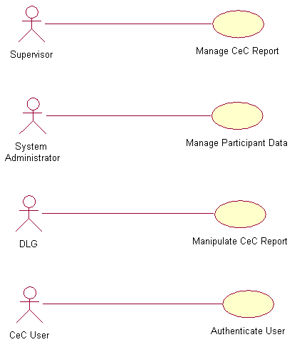
Figure 2.1: Four main RCUMS use case diagrams
The following are the use case diagrams of the main flows and subflows. Every use case diagram is followed by the respective flow-of-event document.
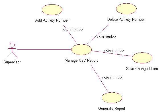
Figure 2.2: Manage CeC Reports use case diagram
1. |
| Use Case : Manage CeC Reports |
| 1.1 | Precondition
Only the appointed supervisors that have the username and password can login into the RCUMS system. The data entry is done weekly.
|
1.2 | Main Flow
This use case starts when the appointed supervisor login into the RCUMS system by entering his/her username and password (E-1). The system verifies the username and password combination validity (E-2). If valid, supervisor is logged into the RCUMS system and prompts supervisor to manage the CeC report. This main flow consists of several sub flows that are:
| |
1.3 | Subflows
S-1: Add activity number.
Based on the given schedule for that week, supervisor adds the CeC’s number of activity. The added number of activity must be new activities conducted on that week.
| |
| S-2: Delete activity number.
Based on the given schedule for that week, supervisor deletes the CeC’s number of activity. The activities that need to be deleted are those that not conducted anymore.
| |
| S-3: Save the changed item
After completing his/her add and/or delete task, supervisor need to save the changed item else the database will not be updated.
| |
| S-4: Generate report
Based on the updated data, the system can generate the weekly report in the graph/chart format. The chart is CeC versus number of activities. From the weekly report the system can generate the monthly (minimum 4 weeks report) and yearly (minimum 12 monthly reports) report. This report need to be generated in order to verify the updated version of the information.
| |
|
| |
1.4 | Alternative Flows
E-1: Supervisor forgot his/her username or/and password. Supervisor needs to fill in his/her email address in the provided field and the use case ends. The system will email the username or password to supervisor.
E-2: When invalid username and/or password entered, supervisor can re-enter the combination three times, then the system will be locked and the use case ends. Supervisor need to wait an hour after the system lock out in order to re-login.
| |
Table 4: Manage CeC report flow-of-event document | ||
|

Figure 2.3: Manage Participant Data use case diagram
2. |
| Use Case : Manage Participants Data |
| 2.1 | Precondition
Only the appointed System Administrator that has the username and password can login into the RCUMS system. The participants’ data are in hardcopy forms collected during the registration session are available.
|
2.2 | Main Flow
This use case starts when the appointed System Administrator login into the RCUMS system by entering his/her username and password (E-1). The system verifies the username and password combination validity (E-2). If valid, supervisor is logged into the RCUMS system and can start managing the participant data that consists the following components:
| |
2.3 | Subflows
S-1: Add participants’ data
Based on the given registration forms for that week, administrator will key-in new participants’ personal data.
| |
| S-2: Delete participants’ data
If there are errors in entering the non-exist participant data, the data need to be deleted.
| |
| S-3: Change participants’ data
When there is an error for the existing participant data, it needs to be changed or updated.
| |
| S-4: Save changed items
After completing his/her add, delete, and/or change participants’ data tasks, administrator need to save the changed item to reflect the updated version.
| |
| S-5: Generate participant statistical information
Based on the updated data, the system can generate the statistical information of the CeC participants. This information includes the age range, education background and occupation
| |
|
| |
2.4 | Alternative Flows
E-1: Administrator forgot his username or/and password. Administrator needs to fill in his/her email address in the provided field and the use case ends. The system will email the username or password to Administrator.
E-2: When invalid username and/or password entered, Administrator can re-enter the combination three times, then the system will be locked and the use case ends. Administrator need to wait an hour after the system lock out in order to re-logon.
| |
Table 5: Manage participant data flow-of-event document | ||
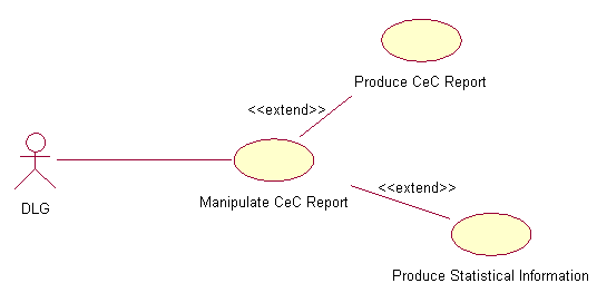
Figure 2.4: Manipulate CeC Report use case diagram
3. |
| Use Case : Manipulate CeC Report |
| 3.1 | Precondition
Only the designated DLG that has the username and password can login into RCUMS system. All the access is read only.
|
3.2 | Main Flow
This use case starts when DLG login into the RCUMS system by entering his/her username and password (E-1). The system verifies the username and password combination validity (E-2). If valid, DLG can start manipulating the CeC report and participants’ statistical information. This main flow consist of the following components:
| |
3.3 | Subflows
S-1: Produce CeC report
From the available menus, DLG can produce the weekly or/and monthly or/and yearly CeC utilization report(s) in graphical form.
| |
| S-2: Produce statistical information
DLG can produce the latest participants’ statistical information such as the total number of participants, highest level of education, age range and mostly enrolled courses per CeC.
| |
|
| |
3.4 | Alternative Flows
E-1: DLG forgot his username or/and password. DLG need to fill in his/her email address in the provided field and the use case ends. The system will email the username or password to supervisor.
E-2: When invalid username and/or password entered, DLG can re-enter the combination three times, then the system will be locked and the use case ends. DLG need to wait an hour after the system lock out in order to re-logon.
| |
Table 6: Manipulate CeC report flow-of-event document | ||
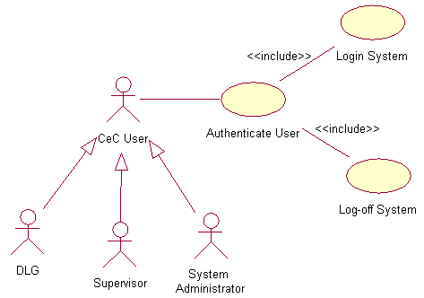
Figure 2.5: Authenticate User use case diagram
4. |
| Use Case : Authenticate User |
| 4.1 | Precondition
Only the designated or appointed users that have username and password can login into RCUMS system.
|
4.2 | Main Flow
This use case starts when user login into the RCUMS system by entering his/her username and password (E-1). The system verifies the username and password combination validity (E-2). If valid, the users will have access to the RCUMS system. This main flow contains the following components:
| |
4.3 | Subflows
S-1: Login system
From the login screen the designated user need to key-in his/her username and password in the given fields. This task is to make sure only the authorized person can access the system.
| |
| S-2: Logoff system
After completing his/her tasks, user has to logoff from the system to prevent unauthorized access.
| |
|
| |
4.4 | Alternative Flows
E-1: User forgot his username or/and password. User needs to fill in his/her email address in the provided field and the use case ends. The system will email the username or password to supervisor.
E-2: When invalid username and/or password entered, user can re-enter the combination three times, then the system will be locked and the use case ends. User need to wait an hour after the system lock out in order to re-logon.
E-3: If user forgets to logoff, the system will auto-logoff after in idle condition for five minutes.
| |
Table 7: Authenticate user flow-of-event document | ||
Note: Because of the time constraint we skip one step in this analysis process, the activity diagram that should be done after the flow-of-event document and use case diagram preparation. We proceed to the next stage, finding classes and building the sequence diagrams.